Introduction
Optical measurement is today an inherent part of research and development in engineering sciences. It is apparent that no measuring technique is entirely precise, and DIC (Digital Image Correlation) Testing is no exception. That said, if it is decided that DIC measurement should be integrated into the R&D workflow or the quality control process, measurement error should be known and expected in advance so that we can make the proper and correct conclusions. Luckily measurement and data included in this report are done with just that topic in mind.
Measuring Set-up
- 3x X-sight DIC 3D M5
- Alpha DIC SW modules: Axial Strain (A)
- Measuring tools: Point probe, Line
- Specimen with stochastic pattern
- Dial indicator
- XY manipulation stage
- Measuring distance: ≈ 270mm

Measurement
The test was devised so that the block with a pattern is moving back and forth (Z direction); the movement cycle was in the range of 0 to 2 millimetres, which should cause large enough error to be detected. The movement is characterized in the diagram below.

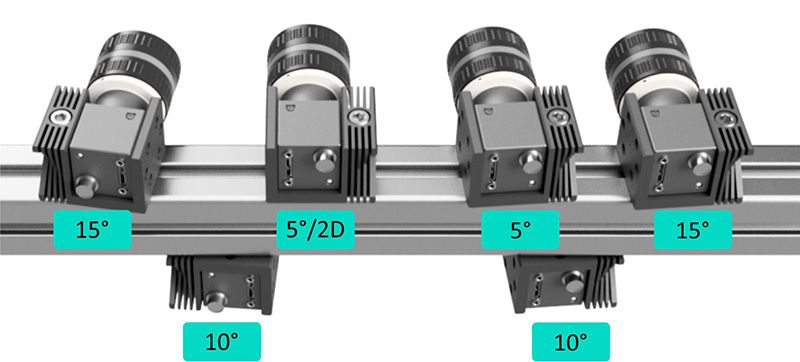
The specimen was measured simultaneously by three 3D DIC systems, which means six cameras set to three stereo pairs. A common stereo angle between the cameras is around 15 degrees, so our set-up includes one pair having an angle of 15°, another pair having 10°, and the last one 5°. This is so that we have a wide understanding of how the error increases with lower camera angles.
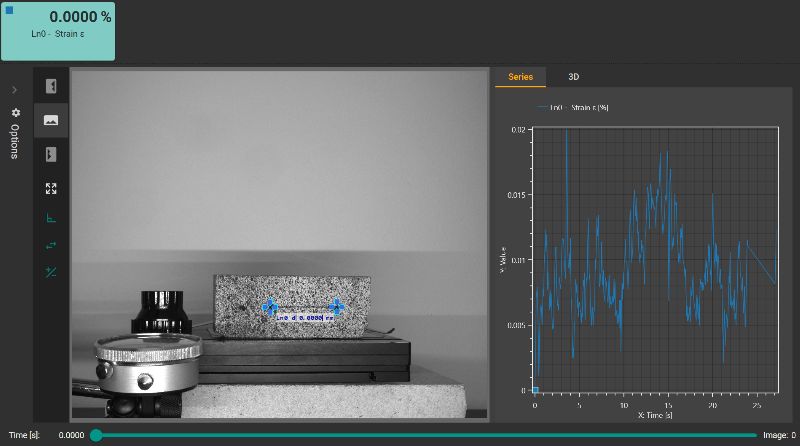
During the experiment, one Line Probe in each stereo pair was used for strain evaluation in Alpha software. The resulting graph then showed the ever-changing value of strain, which, because no actual deformation is happening, gives us the error. In the picture from Alpha software, we can see the minimal and maximal values of the error.
Statistical analysis
Since 2D DIC analysis is much more susceptible to error in out-of-plane movement, it will be used as a baseline.
In the diagram below, we can see how the error is changing over time. The 10° angle is very similar to the 15° at peak; however, 5° has a significant increase at peak value error, meaning it oscillates at larger numbers of up to 0,0075% meanwhile, the other angles hold values around zero with maximal value of 0,005% error.
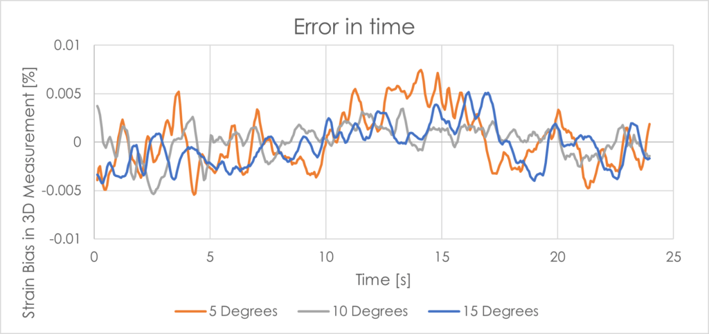

The statistic of measured data shows similar results for the 5° and 10° camera set-up are the average values of error 600 times smaller than the average error in 2D measurement and standard deviation of error are 6000 times smaller than the standard deviation error in 2D measurement.
The 15° camera set-up has the average value of error up to 20 times smaller than the average error in 5° or 10° 3D measurement and standard deviation of error is about half of the standard deviation error in 3D measurement at 5° or 10°.
The average values and standard deviations of 3D measurements of tested movement cycle are as follows:
| 2D | 5 Degrees | 10 Degrees | 15 Degrees | |
|---|---|---|---|---|
| Strain bias average value [‰] | 2,457 | 0,003196 | 0,004083 | 0,000179 |
| Strain bias standart deviation [‰] | 1,210 | 0,000086 | 0,000178 | 0,000045 |
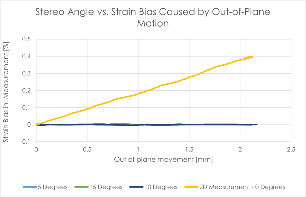
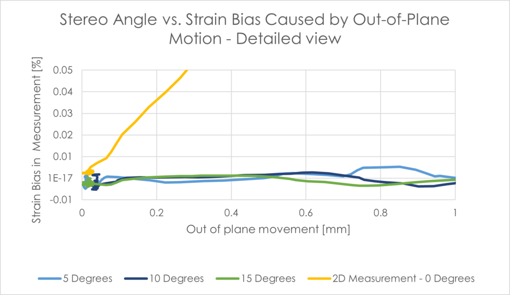
Better understandable is the approach of evaluating the error based on the out-of-plane movement of the specimen. The following diagram shows that the 3D error stays on similar values during the movement. This diagram is generated only for first 2 mm of out of plane movement. 2D, on the other hand, is linearly dependent on the movement and increases proportionally.

Conclusions
The experiment aimed to describe the strain bias happening with different stereo-angle values and determine the influence of the angle size on the output error. The error increases with smaller angles. However, the error is quite small and, on most engineering applications, can be considered, and we can reap the benefits of the larger field of view than normal. The main conclusion, however, here is the staggering difference between 2D and 3D DIC systems.
The measurement data were evaluated in time domain of movement cycle and if we take the largest peak error measured from 3D measurement set, we have still 10 times smaller error than the 2D system @ out of plane deformation of 400 µm, which results in the undeniable benefit of 3D and that is its precision and resistance against outside influences of out-of-plane movement.
However, the 2D measurement and 3D measurement is usually used in very different applications, there are still many fields where 3D measurement is unnecessary for example because there is no movement in the 3rd direction or the movement in 3rd direction is known or negligible.