Introduction
Out-of-plane movement is an issue that can cause a serious deviation during measurement with 2D systems. In the case of simple Tensile tests, if the machine’s construction isn’t sturdy enough or the machine’s grips have some clearance, serious movement in the direction parallel to the camera axis is possible, which 2D systems cannot capture. That’s where this case study comes in and delivers a conclusion to this phenomenon.
Measuring Set-up
- X-sight DIC 2D M5 / DIC 3D M5
- Alpha DIC SW modules: Axial Strain (A), DIC Area, Post Process (PP)
- Aluminium AW5754 Specimen with stochastic pattern

Measurement
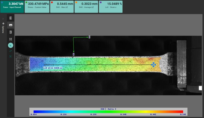
The measurement went in a standard way, the 3D set-up was pointed on the specimen, and the axial strain was measured via a Line Probe. A simultaneous inspection was the DIC Area analysis, which mapped how much the specimen moved in the out-of-plane direction. From the knowledge of an out-of-plane movement, we can estimate a strain bias this motion would create in case of the 2D system was used.

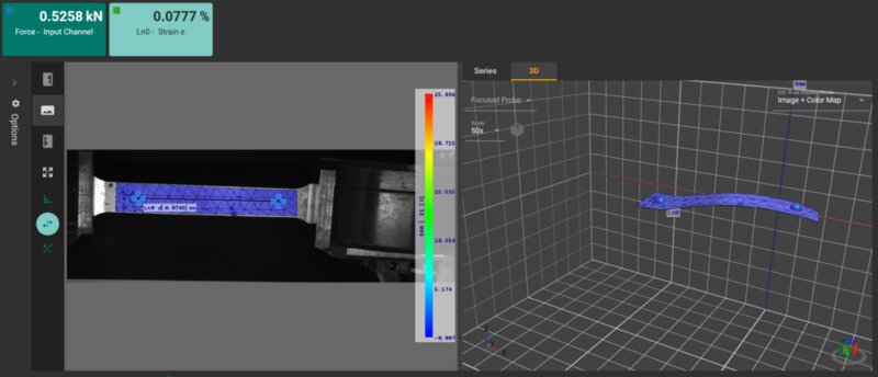
The picture below is taken directly from alpha software, and it clearly shows that the out-of-plain movement is significant though it is shown in exaggerated matter. The wave-like distortion resulted from scaling the deformation, which was about 0.7 mm. This is caused by the machine specification and movement in jaws, but it does project in the overall results of the test.


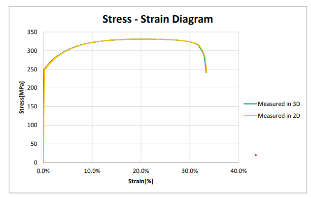
The diagram below shows in green measurements achieved by the 3D system. Measurement in 2D is in the diagram shown in yellow and is noticeably slightly shifted. This shift is caused by a manual projection of the out-of-plane movement – sample position and shape distortion of 0,7 mm.

The result is not significant if the point of measurement is only elongation at break or the elongation at ultimate tensile strength or yield strength. But if we take a closer look at the elastic properties of the specimen and evaluate Young’s modulus or Poisson’s ratio, this value is severely affected.
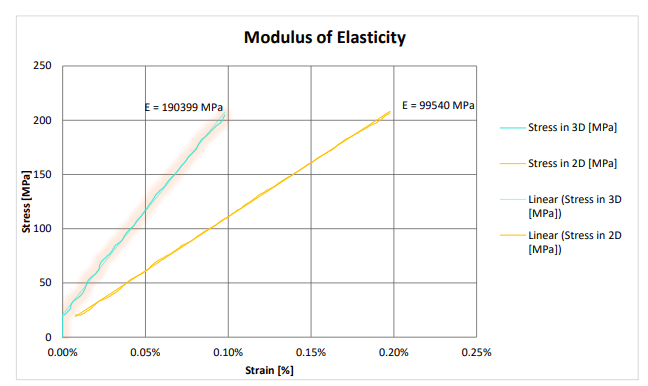
The next diagram shows mentioned shift only in the elastic range of the diagram; though the shift is very small (0.1 %), it results in about 50 % error in the modulus of elasticity calculation.

Conclusion
This study shows how the measured properties of the material decide which optical measuring system should be used. For basic tensile properties like elongation at break or the elongation at ultimate tensile strength or yield strength, the 2D system is fully capable. However, if we want to go one step further and evaluate properties like Young’s modulus or Poisson’s ratio, the 3D system is recommended or even mandatory.